

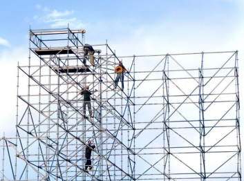
1.Conduct accurate setting-out according to the dimension marks on the support frame configuration drawing. The setting-out range shall be based on the design drawings or the client's requirements, and corrections shall be made during the support frame erection process.
2.After completing the foundation setting-out, place the adjustable base at the corresponding position. Pay attention to the base plate when placing it, and the use of materials with uneven base plates is strictly prohibited. The base wrench can be adjusted to a position about 250mm from the base plate in advance to facilitate elevation adjustment during erection. The main frame sleeve part of the standard base shall be inserted upward into the top of the adjustable base, and the lower edge of the standard base must be completely placed in the groove of the wrench's load-bearing plane. Insert the ledger casting head into the small hole of the disc to make the front end of the ledger casting head abut against the main frame circular tube, and then tighten it by knocking the inclined wedge through the small hole.
3.After the erection of the bottom ledger is completed, level the entire frame to ensure the frame is on the same horizontal plane, and the horizontal deviation of the frame ledger shall not exceed 5mm. The exposed length of the adjustable base screw shall not exceed 300mm, and the height of the bottom ledger from the ground shall not exceed 550mm.
4.Arrange vertical diagonal braces according to the scheme requirements. According to the code requirements and actual erection conditions on site, vertical diagonal braces usually adopt two arrangement forms: one is the matrix spiral form (i.e., lattice column form), and the other is the "八" shaped symmetrical form (or "V" shaped symmetrical form). The specific implementation shall be based on the scheme.
5.Adjust and check the verticality during the frame erection process. The allowable verticality deviation for each step (1.5m high) of the frame is ±5mm, and the allowable overall verticality deviation of the frame is ±50mm or h/1000mm (h is the total height of the frame).
6.The cantilever length of the adjustable support extending from the top ledger or double-channel steel beam support beam shall not exceed 500mm, and the exposed length of the screw shall not exceed 400mm. The insertion length of the adjustable support into the vertical post or double-channel steel beam support beam shall not be less than 200mm.
7.The structural measures such as frame-column connection and anchorage shall comply with the scheme requirements.
Post time: 2025-08-26 16:06:27