

1. Core Erection Process
The erection follows the principle: bottom-up, primary members first, phased forming and progressive stabilization.
1.1 Layout Survey & Foundation Treatment
Locate pole positions strictly per approved special construction scheme based on load transmission paths.
The ground shall be solid, flat and meet bearing capacity; compact, harden or lay base plates if needed. Check adjustable bases for flat undistorted plates and flexible lubricated screws. Pre-set base nut spacing at about 250mm for leveling and ensure full contact between sleeves and nuts for uniform force transfer.
1.2 Main Frame Erection
Insert vertical poles into base sleeves and control verticality strictly. Install ledger cast steel joints into disc holes, hammer wedge pins fully to lock rigid joints. Lay sweeping ledgers immediately after frame assembly to restrict pole bottom displacement.
1.3 Bracing System for Overall Stabilization
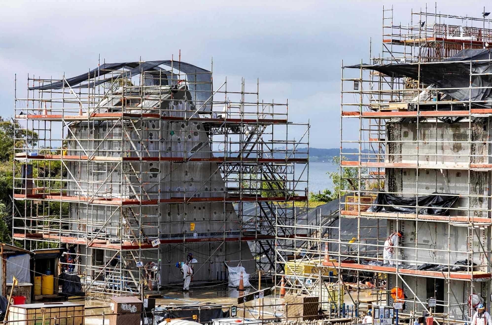
Diagonal braces resist lateral wind and eccentric loads and shall not be omitted. Their cast steel ends are fixed on dedicated large disc holes via wedge pins. Two common layouts: grid spiral layout for heavy-load large-span zones; octagonal/V-shaped symmetric layout for ordinary areas. All layouts shall comply with mandatory requirements of JGJ/T 231.
Wall ties shall be installed on schedule to connect scaffolding with concrete shear walls and columns for lateral restraint and anti-overturning performance, critical for high-rise and cantilever projects.
1.4 Layered Erection & Top Formwork Supports
Repeat the assembly cycle (poles → ledgers → braces) layer by layer. Install adjustable jacks on the top with three mandatory limits: jack overhang ≤500mm, exposed screw length ≤400mm, insertion depth into poles ≥200mm. Lay primary and secondary keels above jacks to complete the formwork support platform.
2. Key Control Indexes
2.1 Dimensional Tolerances
Levelness: Height difference of adjacent ledgers in one bay ≤5mm; overall level deviation ≤1/500 of span and max 50mm.
Verticality: Vertical deviation ≤5mm per 1.5m lift; total vertical deviation ≤1/1000 of total height and max 50mm.
Position deviation of vertical poles ≤10mm.
2.2 Limits for Adjustable Components
Exposed screw length of adjustable base ≤300mm; centerline height of sweeping ledgers above ground ≤550mm. Adjustable jacks shall comply with the three limits mentioned above.
2.3 Mandatory Requirements for Braces & Wall Ties
Diagonal braces shall be arranged as designed with fully hammered wedge pins. Wall ties shall be fixed at designated positions as the last defense against overall collapse under extreme wind loads.
3. Material Inspection, Acceptance & On-site Safety Management
3.1 Incoming Material Inspection
All components shall be supplied with factory certificates. Check poles for no cracks, minor rust (wall thickness loss ≤10%) and no bending; intact vertical welded discs; undamaged cast joints and wedge pins; adjustable parts with complete smooth threads. Defective materials are prohibited on site.
3.2 Construction Supervision & Final Acceptance
Only certified scaffolders are allowed to operate. Foremen, safety officers and supervisors conduct regular inspections on joint tightness, verticality, levelness, braces and wall ties.
Complete special acceptance before formwork construction with full records, in accordance with JGJ/T 231, JGJ 162 and approved construction scheme. Supervise foundation conditions and protective facilities; conduct preloading tests for over-limit projects.
3.3 Safe Operation & Dismantling Rules
No overload stacking on frames. Install sensors for real-time stress and displacement monitoring on ultra-high large-span scaffolding.
Dismantle top-down in reverse erection order: formwork keels → jacks → braces → ledgers → poles. Remove wall ties layer by layer; advance removal is forbidden.
4. Common Site Defects & Industry Development Trend
4.1 Typical On-site Problems
Non-standard substandard pipes with insufficient wall thickness;
Construction inconsistent with special schemes without approval;
Loose, missing or replaced wedge pins causing joint failure;
Over-extended exposed screws of adjustable bases and jacks.
4.2 Industry Development Trend
BIM technology for refined design, collision detection, quantity calculation and visual technical disclosure;
Intelligent IoT monitoring system for real-time stress, tilt and displacement early warning;
Development of self-locking anti-lost wedge pins for safer joints;
Continuous optimization of specifications covering design, erection, acceptance and rental.
Conclusion
The safety and stability of ringlock scaffolding rely on standardized design, qualified raw materials, standardized construction and full-process control. Construction workers shall master its force transmission principle: vertical poles bear compression, ledgers control spacing, braces resist lateral loads, wedge pins lock joints and wall ties prevent overturning. Strictly implement tolerance control, component limits, full bracing and standardized wall ties, together with complete material inspection, process supervision and final acceptance, to fully exert its advantages and secure construction safety. All construction activities shall follow the core principle: safety first, compliant construction and professional guarantee.
Post time: 2026-07-03 09:02:37