

I. Introduction to Ringlock Scaffolding
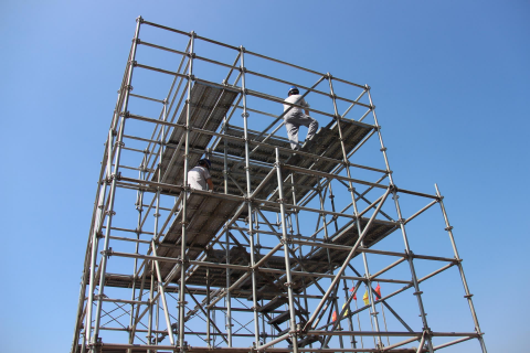
Ringlock scaffolding is a new generation of scaffolding, an upgraded product following bowl-type scaffolding. It is also known as chrysanthemum disc scaffolding, plug-in disc scaffolding, turntable scaffolding, or circular disc scaffolding. Its connection node consists of a disc with a diameter of 133mm and a thickness of 10mm, featuring eight holes. The main components are made of φ48×3.5mm Q345B steel pipes. Vertical poles are steel pipes with a disc welded every 0.50m, and the bottom of the vertical pole is equipped with a connecting sleeve. Horizontal bars are steel pipes with plug-in heads welded at both ends.
II. Classification of Ringlock Scaffolding
According to the technical specification JGJ231-2010, ringlock scaffolding is mainly divided into two models: A and B.
Type A: Commonly referred to as the 60 series, with a vertical pole diameter of 60mm, primarily used for heavy-duty support, such as in bridge engineering.
Type B: The 48 series, with a vertical pole diameter of 48mm, is mainly used in construction, decoration, stage lighting frames, and other fields.
III. Connection Methods of Ringlock Scaffolding Vertical Poles
Based on the connection method of vertical poles, ringlock scaffolding is divided into two forms: outer sleeve connection and inner connecting rod connection.
1.The 60 series ringlock scaffolding on the market generally uses an inner connection.
2.The 48 series ringlock scaffolding generally uses an outer sleeve connection.
IV. Support Scaffolding System of Ringlock Scaffolding
1.Basic Components: Vertical poles, horizontal bars, diagonal braces, positioning bars, base plates, and top supports.
2.Nodes: Discs, horizontal bar castings, diagonal brace castings, and latch plates.
3.Specialized Components: Pedal boards, ladder steps, steel trusses, external hanging tripods, and steel diagonal braces.
4.Supporting Products: Aluminum alloy beams.
5.Adjustable Base: Specifications: H=500mm, 600mm; outer diameter ∅=38mm; wall thickness t=5mm. Function: Adjusts the height of the scaffold base.
6.Starter Bar (Standard Base): Specifications: H=200mm; outer diameter ∅=48mm; wall thickness t=3.2mm. Function: Serves as the starting point for scaffold assembly, with an outer sleeve welded on the top and directly connected to the adjustable base at the bottom.
7.Vertical Pole: Specifications: H=1000mm, 1500mm, 2000mm, 2500mm, 3000mm; outer diameter ∅=48mm; wall thickness t=3.2mm; disc spacing 500mm; vertical pole modulus 500mm; standard base 200mm. Function: Connects with the standard base and serves as the main load-bearing component, with a disc welded every 500mm.
8.Horizontal Bar: Specifications: L=600mm, 900mm, 1200mm, 1500mm; outer diameter ∅=48mm; wall thickness t=2.5mm; material: Q235B; model modulus 300mm, including sizes 300mm, 600mm, 900mm, 1200mm, 1500mm, 1800mm, 2000mm. Function: Both ends are welded with horizontal bar castings and equipped with latch plates, used to interlock with the vertical pole discs, allowing the scaffold to extend outward.
9.Diagonal Brace: Function: Stabilizes the vertical poles, prevents deformation, forms a triangular stable structure, and enhances the overall rigidity of the scaffold.
10.Adjustable Top Support: Specifications: H=500mm, 600mm; outer diameter ∅=38mm; wall thickness t=5mm. Function: Adjusts the top height of the scaffold, with aluminum alloy beams or I-beams placed on top. The theoretical maximum adjustment range of the screw is 100-450mm, but it must be controlled within 100-300mm.
11.Supporting Components: Hook-type steel pedal boards, hook-type steel ladders, hook-type steel ladders with self-locking devices for steel pedal boards.
V. Product Quality Requirements for Ringlock Scaffolding
1.Steel pipes must be free of cracks, dents, and rust; butt-welded steel pipes are not allowed.
2.Steel pipes must be straight, with a straightness tolerance of 1/500 of the pipe length. Both ends must be flat, without bevels or burrs.
3.Castings must have a smooth surface, free of defects such as sand holes, shrinkage cavities, or cracks. Surface sand adhesion must be cleaned.
4.Stamped parts must be free of burrs, cracks, oxide scale, and other defects.
5.The effective height of welds must meet specifications. Welds must be full, and welding slag must be cleaned. Defects such as lack of penetration, slag inclusion, undercut, or cracks are not allowed.
6.Adjustable bases and top supports must be painted or cold-galvanized, with a uniform and durable coating. Components such as vertical poles must be hot-dip galvanized, with a smooth surface and no burrs, nodules, or excess residue at connections.
7.Manufacturer markings on main components must be clear.
VI. Characteristics of Ringlock Scaffolding
1.Low Usage and Light Weight: Typically, the vertical pole spacing is 1.5 meters, and the horizontal bar step distance is 1.5 meters. This reduces the usage by 1/2 and the weight by 1/2 to 1/3 compared to traditional products for the same support volume.
2.High Load-Bearing Capacity: Taking the 60 series heavy-duty support frame as an example, a single vertical pole with a height of 5 meters has an allowable load-bearing capacity of 10.3 tons (safety factor of 2), with a failure load of 22 tons, which is 2-3 times that of traditional products.
VII. Detailed Installation Steps for Ringlock Scaffolding
1.The height of the formwork support should not exceed 24m. If it exceeds 24m, a specialized design is required.
2.Accurately place the adjustable base according to the line position.
3.Adjust the leveling nuts of the adjustable base to ensure they are on the same horizontal plane. The exposed length of the adjustable base screw should not exceed 300mm.
4.Insert the sleeve part of the starter bar upward into the adjustable base, ensuring the lower edge of the starter bar is fully seated in the load-bearing groove of the leveling nut.
5.Place the horizontal bar head into the small hole of the disc, ensuring the front end of the horizontal bar head abuts the main frame pipe. Then, insert the wedge into the small hole and hammer it tight. Bolt connections must ensure they cannot be pulled out after hammering and can self-lock, with a pull-out force of not less than 3kN. The bottom horizontal bar (bottom sweep bar) should be no more than 550mm from the ground.
6.Insert the long end of the vertical pole into the sleeve of the starter bar, check the hole positions, and ensure the straight main frame is inserted to the bottom of the sleeve.
7.Install the second layer of horizontal bars.
8.Install the first layer of diagonal braces: Assemble all "diagonal braces" sequentially in a clockwise or counterclockwise direction. Place the "diagonal brace" into the large hole of the disc, ensuring the front end of the diagonal brace head abuts the main frame pipe. Then, insert the wedge into the large hole and hammer it tight. Note: Diagonal braces are directional and cannot be connected in reverse.
9.Install the third layer of horizontal bars.
10.Install the second layer of diagonal braces: Follow the assembly method in step 6, installing the second layer of "diagonal braces" in the same direction as the first layer.
※ If the first layer is assembled counterclockwise, the second layer and above must also be assembled counterclockwise.
11.Install the U-shaped top support: Insert the toothed pipe of the U-shaped top support into the main frame pipe and adjust the nut to the required height.
The cantilever length of the adjustable top support extending from the top horizontal bar or double-channel steel support beam must not exceed 650mm. The exposed length of the screw must not exceed 400mm, and the insertion length of the adjustable top support into the vertical pole or double-channel steel support beam must not be less than 150mm.
12.Diagonal Brace Installation Requirements:
(1)When the erection height is ≤8m, the step distance should not exceed 1.5m. The first span on all four sides of the scaffold must have vertical diagonal braces at every level. The bottom and top of the scaffold must have vertical diagonal braces. Inside the scaffold, vertical diagonal braces should be installed every 5 spans in both longitudinal and transverse directions, or bow-type steel pipes may be used to set up cross bracing.
(2)When the full hall formwork support height does not exceed 8m and does not exceed 4 steps, top-level horizontal diagonal braces may not be installed. When the scaffold height exceeds 4 steps, top-level horizontal diagonal braces or bow-type steel pipe horizontal cross bracing must be installed.
(3)When the erection height exceeds 8m, vertical diagonal braces must be installed on all sides. The horizontal bar step distance should not exceed 1.5m, and horizontal diagonal braces or bow-type steel pipe horizontal cross bracing should be installed every 4-6 steps in height.
(4)When the formwork support is erected as an independent tower-shaped structure without lateral ties, every step on each side of the scaffold must have vertical diagonal braces. When torsion resistance is required, horizontal diagonal braces or steel pipe horizontal cross bracing should be added at the top and every 3-4 steps.
Post time: 2026-01-30 11:42:38