


1.The foundation shall be leveled, tamped, and its surface hardened with concrete. Ground-supported scaffold poles shall be vertically and stably placed on metal bases or solid backing plates.
2.Longitudinal and transverse bottom rails shall be installed at the bottom of the scaffold poles. The longitudinal bottom rail shall be fixed to the scaffold poles at a position not more than 200mm above the top surface of the base using right-angle couplers. The transverse bottom rail shall be fixed to the scaffold poles immediately below the longitudinal bottom rail using right-angle couplers. When the foundations of scaffold poles are at different heights, the longitudinal bottom rail at the higher level shall extend two spans towards the lower level and be fixed to the scaffold poles. The height difference between the two levels shall not exceed 1m, and the distance from the axis of the scaffold pole on the upper side of the slope to the slope shall not be less than 500mm.
3.A drainage ditch with a cross-section of not less than 200×200mm shall be installed outside the scaffold pole foundation to keep the foundation free of standing water. In addition, the area within 800mm outside the foundation shall be hardened with concrete.
4.External scaffolding shall not be supported on roofs, canopies, balconies, or similar structures. If support on such structures is unavoidable, the structural safety of the roof, canopy, balcony, etc., shall be verified through calculation, and relevant requirements shall be clearly specified in the special construction plan.
5.If there are equipment foundations or pipe trenches under the scaffold foundation, no excavation shall be carried out during the use of the scaffolding. If excavation is necessary, reinforcement measures shall be adopted.
II. Specifications for Erection of Scaffold Poles
1.The height of the first step of the steel pipe scaffold shall not exceed 2m, and the height of other steps shall not exceed 1.8m. The longitudinal spacing of scaffold poles shall not exceed 1.8m, and the transverse spacing shall not exceed 1.5m (preferably 0.85m or 1.05m).
2.When the erection height exceeds 25m, double scaffold poles or a reduced spacing method shall be used. The height of the auxiliary poles in the double-pole setup shall be not less than 3 steps (or not less than 6m).
3.Longitudinal and transverse bottom rails must be installed for the first-step scaffold poles. The longitudinal bottom rail shall be fixed to the scaffold poles at a position not more than 200mm above the top surface of the base using right-angle couplers, and the transverse bottom rail shall also be fixed to the scaffold poles below the longitudinal bottom rail using right-angle couplers.
4.The bottom-layer scaffold poles, bottom rails, and diagonal braces shall all be painted with yellow-black or red-white alternating warning colors.
III. Specifications for Setting Up Scaffold Members
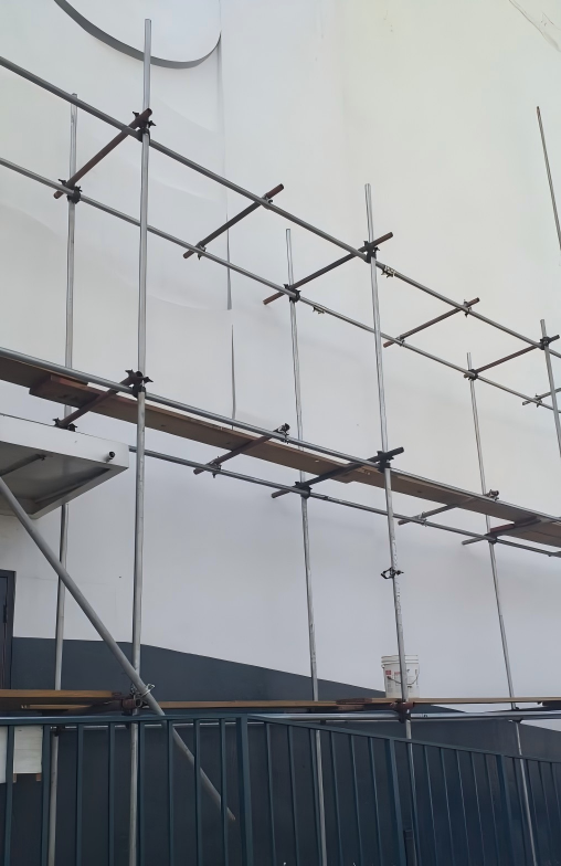
1.Transverse horizontal members shall be installed at the joints where scaffold poles intersect with longitudinal horizontal members, and both ends of the transverse horizontal members shall be fixed to the scaffold poles to ensure safe force transmission.
2.Except for the top step of the top layer, scaffold poles can be extended by lapping; for all other steps, butt joints must be used. When lapping is adopted, the lap length shall not be less than 1m, and no fewer than 3 swivel couplers shall be used for fixation.
3.During the use of the scaffolding, the longitudinal and transverse horizontal members at the main nodes are strictly prohibited from being removed.
4.Longitudinal horizontal members shall be installed on the inner side of the scaffold poles, with a length of not less than 3 spans.
5.Longitudinal horizontal members shall be connected by butt couplers or lapping. For butt joints, the butt couplers of longitudinal horizontal members shall be arranged in a staggered manner. For lapping, the lap length of longitudinal horizontal members shall not be less than 1m, and 3 swivel couplers shall be installed at equal intervals for fixation. The distance from the edge of the coupler cover plate at the end to the end of the lapped longitudinal horizontal member shall not be less than 100mm.
6.The length of both ends of transverse horizontal members extending beyond the edge of the coupler cover plate shall not be less than 100mm, and the extension lengths shall be kept as consistent as possible.
7.Lapping or butt joints of adjacent members must be staggered by one span, and the number of joints in the same plane shall not exceed 50%.
IV. Specifications for Setting Up Diagonal Braces and Transverse Diagonal Braces
1.Diagonal braces shall be continuously installed from the bottom corner to the top along the length and height of the scaffolding.
2.The diagonal rods of diagonal braces shall be connected to the extended ends of scaffold poles or transverse horizontal members. The extension of diagonal rods shall be done by lapping, with an inclination angle of 45°~60° (45° is preferred). Each diagonal brace shall span 5~7 scaffold poles, with a width of not less than 4 spans (or not less than 6m).
3.Transverse diagonal braces must be installed at both ends of open-type double-row scaffolding, and additional transverse diagonal braces shall be installed every 6 spans in the middle.
4.Diagonal braces and transverse diagonal braces shall be erected simultaneously with scaffold poles and longitudinal/transverse horizontal members.
5.The lap length of diagonal braces shall not be less than 1m, and no fewer than 3 swivel couplers shall be used for fixation.
V. Specifications for Scaffold Planks and Guardrails
1.Scaffold planks shall be fully laid on each step of the external scaffolding.
2.Scaffold planks shall be laid horizontally and vertically, fully covering the required area without gaps.
3.The four corners of each scaffold plank shall be firmly bound with double-stranded 18-gauge galvanized wire. The joints of scaffold planks shall be flat, and no overhanging planks (protruding beyond the support) are allowed. Damaged scaffold planks shall be replaced promptly.
4.The outer side of the scaffolding shall be enclosed with qualified dense-mesh safety nets, which shall be fixed to the inner side of the outer scaffold poles using 18-gauge galvanized wire.
5.A 180mm-high toeboard (or toe rod) shall be installed on each step of the outer side of the scaffolding. In addition, guardrails made of the same material shall be installed at heights of 0.6m and 1.2m. If an edge is formed on the inner side of the scaffolding, guardrails shall be installed in the same way as the outer side.
6.For flat roofs, the outer scaffold poles shall extend 1.2m above the roof eave. For sloped roofs, the outer scaffold poles shall extend 1.5m above the roof eave.
VI. Specifications for Connecting Scaffolding to the Building (Wall Connectors)
1.Wall connectors shall be installed close to the main nodes, with a deviation distance from the main nodes not exceeding 300mm. If the deviation exceeds 300mm, reinforcement measures shall be adopted. When a wall connector is located near 1/2 of the step height of the scaffold pole, adjustments must be made.
2.Wall connectors shall be installed starting from the longitudinal horizontal member of the first step at the bottom layer. If installation at this position is difficult, other reliable fixing measures shall be used. Wall connectors shall be arranged in a diamond pattern, or alternatively in a square or rectangular pattern.
3.Rigid wall connectors shall be used to connect the scaffolding to the building.
4.Wall connectors shall be installed horizontally. If horizontal installation is not feasible, the end connected to the scaffolding shall be connected at a downward slope; upward-slope connections are strictly prohibited.
5.The spacing of wall connectors shall comply with the requirements of the special construction plan: the horizontal spacing shall not exceed 3 spans, and the vertical spacing shall not exceed 3 steps (or not exceed 4m). For scaffolding with a height of over 50m, the vertical spacing shall not exceed 2 steps. Wall connectors shall be densely installed within 1m of building corners and within 800mm of the top of the scaffolding.
6.Wall connectors must be installed at both ends of open-type scaffolding, with a vertical spacing not exceeding the floor height of the building (or not exceeding 4m or 2 steps).
7.The scaffolding shall be erected in line with the construction progress, and the height of one-time erection shall not exceed two steps above the adjacent wall connectors.
8.During the use of the scaffolding, the removal of wall connectors is strictly prohibited. Wall connectors must be removed layer by layer along with the scaffolding; it is forbidden to remove all wall connectors of one or multiple layers first before dismantling the scaffolding. The height difference during segmented dismantling shall not exceed two steps; if the height difference exceeds two steps, additional wall connectors shall be installed for reinforcement.
9.If existing wall connectors need to be removed for construction purposes, reliable and effective temporary bracing measures shall be adopted to ensure the safety of the external scaffolding.
10.For scaffolding with a height exceeding 40m where wind vortex effects may occur, wall connectors capable of resisting upward overturning forces shall be adopted.
VII. Specifications for Internal Enclosure of the Scaffolding
1.The clear distance between the inner scaffold poles and the building wall shall generally not exceed 200mm. If this requirement cannot be met, standing plates shall be laid, and the standing plates shall be flat and firm.
2.Horizontal enclosed isolation shall be provided between the scaffolding and the building at every 3 steps below the construction layer. Horizontal enclosed isolation shall also be installed at the first layer and the top layer.
VIII. Specifications for Ramp of External Scaffolding
1.The ramp shall be attached to the outer side of the scaffolding and shall not be cantilevered. The ramp shall be erected in a zigzag shape, with a slope not steeper than 1:3 and a width not less than 1m. The area of the platform at the turning point shall not be less than 3m². The scaffold poles for the ramp shall be installed independently and shall not share the poles of the main scaffolding. In addition, connections shall be installed for the ramp poles at each step or each longitudinal span in both longitudinal and transverse directions.
2.A 180mm-high toeboard (or toe rod) shall be installed on both sides of the ramp and around the turning platform. Guardrails made of the same material shall also be installed at heights of 0.6m and 1.2m, and the ramp shall be enclosed with qualified dense-mesh safety nets.
3.Diagonal braces shall be installed on the side of the ramp and the outer side of the platform.
4.Scaffold planks on the ramp shall be laid horizontally, and anti-slip strips shall be installed every 300mm. The anti-slip strips shall be made of 20×40mm square timber and firmly bound with multi-strand wire.
IX. Specifications for Erection of Scaffold Openings
1.Scaffold openings shall adopt a truss structure with ascending diagonal rods and parallel chord rods, where the angle between the diagonal rods and the ground shall be 45°~60°.
2.The splayed support rods shall be made of full-length members.
3.The splayed support rods shall be fixed to the extended ends of transverse horizontal members or the inter-span transverse horizontal members using swivel couplers.
4.The two scaffold poles on both sides below the opening truss shall be double poles, and the height of the auxiliary poles shall be 1~2 steps higher than the opening.
5.Anti-slip couplers shall be installed at the extended ends of the upper and lower chord rods of the opening truss, and these anti-slip couplers shall be close to the couplers at the main nodes.
Post time: 2025-11-04 10:12:54