

(1) Based on the outer diameter of the vertical poles, scaffolding can be classified into Standard Type (B-type) and Heavy Duty Type (Z-type). The quality of scaffolding components, materials, and their manufacturing must comply with the current industry standard "JG/T 503 Components for Cuplock Steel Tube Supports".
(2) The pin connection between the pole end socket and the connecting base plate (cup) should be self-locking upon hammering and not pull out. During erection, use a hammer weighing not less than 0.5kg to strike the top of the pin at least twice until tight; after tightening, strike again, and the pin's settlement should not exceed 3mm.
(3) After the pin is tightened, the arc surface of the socket should fit flush against the outer surface of the vertical pole.
(4) The structural design of the scaffolding should adopt different safety grades according to the scaffold type, erection height, and loads. The safety grade classification should comply with the provisions in the table below. [Note: Table content not provided in original text]
II. Scaffolding Construction Requirements
(A) General Provisions
(1) The scaffolding construction system shall be complete and possess overall stability.
(2) Select fixed-length ledger bearers (horizontal bearers) and diagonal braces based on the calculated longitudinal and transverse spacing of vertical poles from the construction plan, and configure vertical poles, base jacks, adjustable u-heads (forkheads), and adjustable base jacks according to the erection height.
(3) The lift height (vertical spacing between ledgers) of the scaffolding should not exceed 2m.
(4) Diagonal bracing for the scaffold frame shall not be connected using steel tube couplers (traditional clamps).
(5) When the design load value for Standard Type (B-type) vertical poles exceeds 40kN, or for Heavy Duty Type (Z-type) vertical poles exceeds 65kN, the first lift height of the scaffolding should be reduced by 0.5m compared to the standard lift height.
(B) Structural Requirements for Support Frames (Shoring/Falsework)
(1) The height-to-width ratio of the support frame should be controlled within 3; if the ratio exceeds 3, anti-overturning measures such as rigid connections to existing structures must be taken.
(2) For support frames with a standard lift height of 1.5m, arrange vertical diagonal bracing and select the bracing layout pattern based on the erection height, frame model, and the design value of the axial force on the vertical poles.
(3) When the erection height of the support frame exceeds 16m, vertical diagonal bracing should be installed in every bay within the top lift.
(4) The cantilever length of the adjustable u-head (forkhead) extending from the centerline of the top ledger or the double-channel support beam in a support frame should not exceed 650mm. The exposed length of the screw should not exceed 400mm, and the length inserted into the vertical pole or double-channel beam should not be less than 150mm.
(C) Provisions for Adjustable U-heads (Forkheads) and Base Jacks
(1) The insertion length of the screw of an adjustable base jack into the vertical pole should not be less than 150mm, and the exposed length of the screw should not exceed 300mm. The distance from the centerline of the bottom ledger (serving as the kicker ledger) to the base plate of the adjustable base jack should not exceed 550mm.
(2) When the erection height of the support frame exceeds 8m and there are existing building structures nearby, it should be reliably tied to the surrounding structures at every 4 to 6 lifts in height.
(3) Horizontal cross bracing (scissor bracing) should be installed at every 4 to 6 standard lift heights along the height of the support frame, complying with the relevant provisions for steel tube horizontal scissor bracing in the current industry standard "JGJ 130 Safety Technical Code for Steel Tube Scaffolding with Couplers in Construction".
(4) When a support frame is erected as an independent tower, it should be horizontally tied to adjacent independent towers at every 2 to 4 lifts in height.
(5) When creating a pedestrian passageway within the support frame that is the same width as a single ledger bearer, the bottom ledger and diagonal braces can be selectively removed at intervals to form the passage, with vertical diagonal bracing installed between the vertical poles on both sides orthogonal to the passage direction. When creating passageways of different widths, a support beam should be erected above the passage; the beam model and spacing are determined based on the load. The vertical pole spacing in the bays adjacent to the passage supporting the beam should be determined by calculation, and the support frame around the passage should be connected integrally. The opening at the top should be fully covered with protective decking. Safety nets should be installed in adjacent bays. Safety warnings and anti-collision facilities should be installed at openings for vehicle passage.
(D) Scaffolding Construction Requirements (Access Scaffolding)
(1) The height-to-width ratio of the scaffolding should be controlled within 3; if the ratio exceeds 3, anti-overturning measures such as guy ropes should be installed (refer to diagram for guy ropes).
(2) When erecting double-row external scaffolding or when the erection height is ≥ 24m, select the frame geometric dimensions based on usage requirements, and the adjacent ledger lift height should not exceed 2m.
(3) For double-row external scaffolding, vertical poles of different lengths should be used staggered arrangement at the first level. Adjustable base jacks or sole plates should be configured at the bottom of the vertical poles.
(4) When creating a pedestrian passageway in double-row external scaffolding, a support beam should be installed above the passage; the beam cross-section is determined based on span and load. Additional diagonal bracing should be added to the scaffolding on both sides of the passage. The opening at the top should be fully covered with protective decking. Safety nets should be installed on both sides. Safety warnings and anti-collision facilities should be installed at openings for vehicle passage.
(5) Vertical diagonal bracing should be installed on the external facade of double-row scaffolding, complying with:
① Continuous diagonal bracing should be installed from bottom to top at corners and at both ends of open-type scaffolding.
② Continuous vertical or inclined diagonal bracing should be installed every 4 bays; when the frame height exceeds 24m, install diagonal bracing every 3 bays.
③ Continuous vertical diagonal bracing should be installed between adjacent external vertical poles of the double-row scaffold from bottom to top.
(6) The installation of tie-ins (wall connectors) should comply with:
① Tie-ins should be rigid members capable of resisting tension and compression loads, firmly connected to the main building structure and the scaffold frame.
② Tie-ins should be installed close to the ledger bearer node points.
③ Tie-ins on the same floor should be on the same level plane, with a horizontal spacing not exceeding 3 bays. The cantilever height of the frame above the tie-ins should not exceed 2 lifts.
④ At frame corners or both ends of open-type double-row scaffolding, tie-ins should be installed per floor level, with a vertical spacing not exceeding 4m.
⑤ Tie-ins should start from the first level ledger at the base, arranged in a diamond or rectangular pattern, with connection points evenly distributed.
⑥ When tie-ins cannot be installed at the base of the scaffolding, consider erecting multi-row scaffolding with diagonal bracing to form an additional ladder frame on the outward-leaning face.
III. Installation and Dismantling
(A) Construction Preparation
(1) Before scaffolding construction, a special construction plan should be prepared based on site conditions, ground bearing capacity, and erection height, and implemented after approval.
(2) Operators should receive professional technical training, pass assessments, and hold certificates. Technical and safety briefings based on the special construction plan should be conducted before erection.
(3) Accepted qualified components should be sorted and stored by type and specification, with quantity and specification labels. The storage area should have good drainage and be free of standing water.
(4) Embedded parts such as tie-in anchors, bracket bolts, or suspension beam fixing bolts/rings should be pre-embedded according to the design requirements.
(5) The scaffolding erection site should be level and firm, with drainage measures implemented.
(B) Content of Construction Plan
The special construction plan should include: basis of compilation, project overview, construction arrangement, construction technology and techniques, safety and quality assurance measures, construction management and operator allocation, acceptance requirements, emergency measures, calculations, and drawings.
(C) Foundation and Base Jacks
(1) The scaffolding foundation should be constructed according to the special construction plan and accepted based on ground bearing capacity requirements before erection can commence.
(2) For soil foundations, adjustable base jacks and sole plates should be used under vertical poles; the sole plate length should not be less than 2 spans.
(3) For significant foundation height differences, utilize the node level differences of the vertical poles in conjunction with adjustable base jacks for adjustment.
(D) Support Frame Installation and Dismantling (Formwork Support)
(1) The location of support frame vertical poles should be determined according to the special construction plan.
(2) The support frame should be erected based on the positioning of the adjustable base jacks for the vertical poles, forming basic units in the sequence of "vertical pole → ledger bearer (horizontal bearer) → diagonal brace" before expanding into the overall system.
(3) Adjustable base jacks should be placed on the positioning lines and kept level. If sole plates are needed, they should be flat; warped or cracked wooden sole plates must not be used.
(4) When erecting multi-layer continuous support frames, the vertical poles of upper and lower layers should be coaxial.
(5) After erection, the support frame should be inspected and confirmed to comply with the special construction plan before proceeding to the next construction stage.
(6) After installation of adjustable base jacks and u-heads, the outer surface of the vertical pole should fit flush with the adjustable nut; the difference between the outer diameter of the vertical pole and the inner diameter of the nut step should not exceed 2mm.
(7) After installation of pins for ledger bearers and diagonal braces, hammer strike inspection should be performed; the continuous settlement should not exceed 3mm.
(8) During frame hoisting, additional pole connection components should be added for vertical pole connections.
(9) During frame erection and dismantling, small components like adjustable base jacks and u-heads should be passed manually by hand; lifting operations should be directed by designated personnel, and collision with the frame should be avoided.
(10) After erection, the verticality deviation of vertical poles should not exceed 1/500 of the total height of the support frame, and not more than 50mm.
(11) Dismantling should follow the principle of "dismantle in reverse order of assembly", starting from the top and proceeding layer by layer. Working simultaneously at different levels is prohibited. Throwing materials is strictly prohibited.
(12) For segmented or facade-by-facade dismantling, a technical plan for the boundary should be determined to ensure the stability of the remaining sections.
(E) Scaffolding Installation and Dismantling (Access Scaffolding)
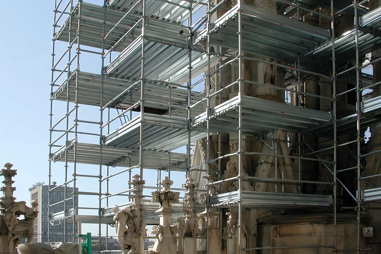
(1) Scaffold vertical poles should be accurately positioned and erected according to the construction progress. The erection height of double-row external scaffolding should not exceed 2 lifts above the highest tie-in, and the free-standing height should not exceed 4m.
(2) Tie-ins for double-row external scaffolding should be installed synchronously as the frame rises, at specified locations, and must not be installed lagging behind or arbitrarily removed.
(3) The setup of the working platform should comply with:
① The platform should be fully decked.
② Toe boards and guardrails should be installed on the outside of double-row external scaffolding. Guardrails can consist of two horizontal rails at the 0.5m and 1.0m connection points on the uprights at each level, with close-mesh safety nets hung on the outside.
③ Gaps between the working platform and the main structure should be protected with horizontal safety nets.
④ When steel decking plates are used, the hooks should be engaged with the ledger bearers and locked in place.
(4) Reinforcement members and diagonal bracing should be erected synchronously with the scaffolding. When using couplers and steel tubes, comply with the requirements of standard JGJ130.
(5) The height of the external guardrail at the top lift of the scaffolding should be not less than 1500mm above the top working platform level.
(6) When vertical poles are in tension, the extended connection part of the pole sleeve should be connected using bolts.
(7) Scaffolding should be erected and used in sections, and can only be used after acceptance.
(8) Scaffold dismantling should only commence after confirmation by the project manager and issuance of a dismantling permit.
(9) During dismantling, a safe area should be demarcated, warning signs posted, and designated personnel assigned for supervision.
(10) Before dismantling, equipment, excess materials, and debris on the scaffold should be cleared.
(11) Dismantling should follow the "reverse order of assembly" principle; working simultaneously at different levels is not allowed. Tie-ins for double-row external scaffolding should be removed layer by layer as the frame is dismantled; the height difference between dismantling sections should not exceed 2 lifts. If site conditions require a greater height difference, additional tie-ins must be added for reinforcement.
(F) Inspection and Acceptance
(1) Acceptance of scaffolding components entering the site should include: product identification, quality certificate, type inspection report; main technical parameters and user manual; sampling inspection and full-frame testing if quality is doubtful.
(2) Support frames and scaffolding should be accepted under these circumstances: after foundation completion, before frame erection; for high-formwork supports over 8m, after every 6m height completed; after reaching design height, before concrete pouring; before reuse after being idle for over 1 month; after events like winds force 6 or higher, heavy rain, or thawing of frozen ground foundations.
(3) Support frame acceptance should confirm: foundation conforms to design, level and firm, vertical poles have no looseness or suspension from foundation, base jacks and sole plates meet requirements; frame erection conforms to design, diagonal bracing, scissor bracing, etc., are installed per code; cantilever length of adjustable u-heads and base jacks meets requirements; pins for ledger bearers and diagonal brace sockets are tightened into the connection plates.
(4) Scaffolding acceptance should confirm: frame erection conforms to design, diagonal bracing or scissor bracing is installed compliantly; no uneven settlement under vertical poles, adjustable base jacks contact foundation without looseness or suspension; tie-ins conform to design, reliably connected to main structure and frame; external safety vertical nets, internal horizontal nets, and guardrails are complete and secure; components for reuse undergo visual inspection and recording before use; construction and quality inspection records are timely and complete; pins for ledger bearers and diagonal brace sockets are tightened into the connection plates.
(5) Preloading of support frames (if required) should comply: a special preloading plan is prepared, safety and technical briefing conducted before preloading; preloading load layout simulates actual structural load distribution, preloading is done symmetrically in stages; preloading monitoring and loading stages comply with "JGJ/T 194 Technical Specification for Preloading of Full Frame Steel Tube Supports".
Post time: 2025-10-11 10:26:32