

1. Quality Requirements for Scaffolding Components
1.1 Steel Pipes
National standard No.3 welded steel pipes with outer diameter 48mm and wall thickness 3.5mm shall be adopted. Each batch shall come with valid factory certificates and test reports. Pipes with severe rust, deformation, cracks or indentations are prohibited.
Qualified pipes feature smooth surfaces without cracks, scars or hard bends. All pipes receive anti-rust coating: vertical poles and longitudinal ledgers in yellow paint; cross braces and guardrails in alternating red and yellow warning paint. Single pipe weight shall not exceed 25kg, and unauthorized drilling is forbidden.
Unified length specifications: vertical & longitudinal ledgers 3–6m; transverse ledgers 1.1–1.3m; diagonal braces 3–4m.
1.2 Scaffold Couplers
New couplers shall be equipped with production licenses, certificates and test reports. Reused couplers must undergo full re-inspection; cracked or permanently deformed couplers shall be scrapped, and slippery damaged bolts replaced. All couplers are anti-rust treated with regular bolt lubrication for flexible rotation.
Couplers shall fit tightly against pipes with opening clearance ≤5mm. No cracking or deformation shall occur when bolts are tightened to a torque of 65N·m.
2. Structural Design & Erection Specifications
2.1 Structural Parameters
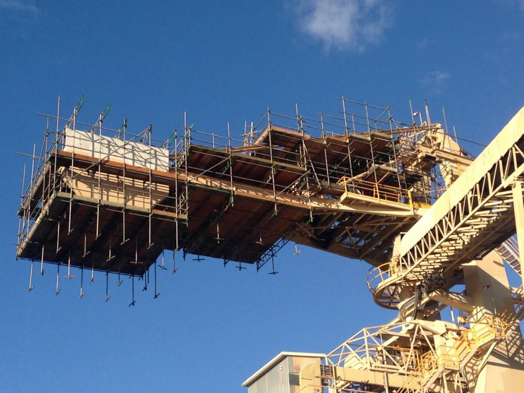
This project adopts 16# I-steel cantilever single-pole double-row external scaffolding:
Lift height: 1.8m; vertical pole longitudinal spacing: 1.5m; transverse spacing between inner & outer rows: 0.85m. Auxiliary ledgers are installed beneath transverse ledgers to improve frame rigidity.
2.2 Standard Erection Process
Cantilever Beam Installation
Embed lifting rings per drawings for precise positioning. Lay 16# I-steel beams after setting out, level and fix via steel bar welding. Handle beams gently to avoid damage to concrete structures.
Overall Erection Sequence
Start erection from building corners and extend outward: erect vertical poles → install bottom longitudinal ledgers on cantilever beams → lay transverse ledgers → mount multi-layer ledgers & temporary wall ties → splice extended poles → install cross braces & diagonal braces → erect guardrails & toe boards → fully lay scaffold boards → install horizontal & vertical safety nets.
Key Erection Notes
Calibrate vertical pole plumb before fixing base parts. Inspect all spacing and verticality after each layer erection before installing wall ties. Scaffold height shall not exceed two lifts above the nearest wall tie to maintain stability and synchronize with main structure construction.
2.3 Detailed Technical Erection Requirements
Bottom Horizontal Supports
Bottom longitudinal ledgers are fixed to poles with right-angle couplers within 100mm above the base, with transverse ledgers fastened underneath.
Vertical Poles
Only rust-proof straight pipes are used. Pole tops extend 1.5–1.8m above working surfaces. Butt joints are staggered vertically by ≥500mm, with joint centers no more than 1/3 of lift height from main nodes.
Longitudinal Ledgers
Mounted inside poles and span no less than 3 bays. Continuous closed frames are formed at corners with staggered butt joints spaced ≥500mm horizontally.
Transverse Ledgers
Mandatory at all main nodes, extending ≥100mm outward and ≥200mm inward with ≤100mm gap from walls. Axis offset from main nodes ≤150mm.
Coupler Tightening Standards
Matching couplers with bolt torque controlled at 40–50N·m (max 60N·m). Center distance of couplers at main nodes ≤150mm. Pipe ends extend ≥100mm beyond coupler covers.
Wall Tie Connections
Wall ties are fixed to embedded steel pipes with double couplers, arranged in 2-lift & 3-bay layout (vertical 3.6m, horizontal 4.5m). Ties act horizontally on both inner and outer poles; downward diagonal layout is allowed while upward diagonal is forbidden. Ties start from the first lift with staggered diamond layout within 300mm of main nodes. I-steel cantilevers are reinforced with steel wire ropes.
Cross Bracing
Continuous full-height cross braces covering 5 vertical poles are erected synchronously. Diagonals lap over 1m with 3 evenly distributed couplers, forming a 45°–60° angle with ground.
Scaffold Board Laying
Boards rest on three transverse ledgers with reserved 300mm gap from walls. Single cantilever length 130–150mm, lap length over 200mm. Boards are secured with No.18 iron wire without gaps on operation floors.
Frame Enclosure & Outer Protection
900mm-high guardrails are set for each lift. Dense safety nets are fully hung along outer poles, with full wooden formwork enclosure every three cantilever floors.
3. Allowable Deviation Standards for Erection Quality
Vertical pole plumbness: ≤1/300 of frame height, maximum absolute deviation ≤75mm; overall height deviation ≤100mm
Longitudinal ledger levelness: height difference between two ends ≤20mm, linear deviation ≤1/300 of length, cross-span height difference ≤10mm
Transverse ledger levelness deviation ≤10mm
Lift height & transverse pole spacing tolerance ≤20mm; longitudinal pole spacing tolerance ≤50mm
Wall ties must be accurately positioned and firmly fixed
Safety nets shall be qualified, intact and tightly bound
Steel mesh fixed with No.18 iron wire without warping
I-steel and steel wire ropes for cantilevers must comply with standards
4. Safety Technical Measures for Erection & Usage
Erection workers must hold valid operation certificates and pass regular physical examinations.
Full PPE including safety helmets, harnesses and anti-slip shoes is mandatory. Warning barriers and on-site supervisors are required during erection.
Components and finished frame must pass full acceptance before use.
Regular inspection during service: connections, foundation drainage, coupler tightness, verticality and complete protective measures; overloading is prohibited.
Unauthorized removal of main node members, sweeping ledgers and wall ties is strictly forbidden.
No horseplay on scaffolding; leaning on guardrails is banned.
Stacking heavy materials such as steel bars and formwork on cantilever scaffolding is prohibited.
Random connection between external cantilever scaffold and interior full framing is disallowed.
Stop construction and reinforce frame stability under heavy rain or strong wind.
All scaffolding work shall cease during thunderstorms, gales and heavy rain.
Re-inspection and acceptance are required before reuse after long-term shutdown.
All erection activities shall strictly follow the special construction scheme.
Post time: 2026-06-29 09:06:06