


1. Construction of Ground-Based Double-Row Scaffolding
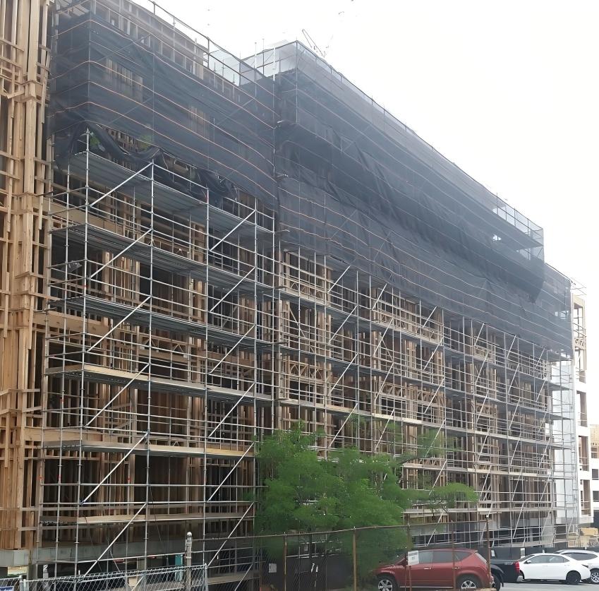
The ground-based double-row scaffolding is erected using φ48×3.5 steel pipes, with a maximum erection height of 24m. The standard parameters are: longitudinal spacing of uprights of 1.5m, transverse spacing of 1.05m, and vertical spacing of ledger beams of 1.8m. The distance from the inner row of uprights to the wall is 0.3m. After the ground soil is compacted, a 100mm thick C15 concrete cushion layer is poured. A full-length scaffold plank is laid at the base of the uprights. Longitudinal and transverse sweeper beams are installed 200mm above the ground level. Bamboo mats are laid on each putlog. On the outer side, a 250mm high toe board is installed on each putlog, with handrails at heights of 600mm and 1200mm. The outer side is covered with green close-mesh safety netting, and the top three steps are fitted with a 180mm high kickplate. The scaffold tie points are arranged at intervals of two steps and three spans, using double couplers for connection.
(1) During erection, the joints of adjacent uprights shall be staggered and located in different lift intervals, with the distance from adjacent ledger beams not exceeding one-third of the lift height. Uprights and ledger beams must be fastened tightly with right-angle couplers; omission or skipping steps is prohibited. Except for the topmost lift and step, all other upright extensions shall use butt couplers, with the distance from the edge of the coupler cover to the pipe end being not less than 100mm. The vertical deviation of uprights shall not exceed 1/300 of the scaffold height, with an absolute maximum deviation controlled within 50mm.
(2) Ledger beams are installed on the inner side of the uprights. The length of a single beam shall not be less than 3 spans. They are set according to the floor height, with two steps per floor, and spacing not exceeding 1500mm, meeting design requirements. Members are connected using butt or lap joints: During erection, ledger beam joints shall be staggered in different longitudinal bays, with a stagger distance not less than 500mm; lap lengths shall be not less than 1m, and the distance to adjacent uprights shall not exceed 1/3 of the longitudinal spacing.
(3) Putlogs are placed close to the uprights, erected on the ledger beams and fastened with right-angle couplers. A putlog must be installed at each main node and must not be removed. The center-to-center distance between the two right-angle couplers at a main node shall not exceed 150mm. The extension length of the putlogs on the outer upright side shall be controlled between 150mm and 300mm for easy hanging of the safety net and ensuring the facade appearance. The extension length of the putlog near the wall shall be not less than 100mm and not more than 300mm, with the distance to the finishing surface not exceeding 100mm. On the working platform, at non-main nodes, putlogs are spaced equidistantly according to the need to support the platform planks, with a maximum spacing not exceeding half the longitudinal spacing of the uprights. One or two additional putlogs may be added between adjacent uprights as needed. Removing putlogs that serve as basic structural components is strictly prohibited.
(4) Diagonal bracing is installed continuously on the external facade of the scaffold, erected continuously from bottom to top, and must be erected simultaneously with the uprights, longitudinal, and transverse horizontal members. The diagonal braces are fixed to the intersecting uprights or ledger beams using swivel couplers. The distance from the center of the swivel coupler to the main node shall not exceed 150mm. The angle between the diagonal brace and the ground shall be between 45° and 60°, and it must be reliably connected to the basic structural members of the scaffold, with firm nodal connections. The tightening torque for coupler bolts shall be 40 N·m to 65 N·m.
(5) The vertical deviation of scaffold uprights shall be ≤ 1/300, and the maximum absolute vertical deviation shall not exceed 50mm.
(6) The levelness deviation of scaffold horizontal members shall be ≤ 1/250, and the overall levelness deviation of the entire scaffold length shall not exceed 50mm.
(7) The scaffold must be re-inspected and accepted before further use under the following circumstances during its service life: after continuous use for 6 months; after being out of service for more than 15 days during construction, before reuse; after being subjected to strong factors such as storms, heavy rain, or earthquakes; or if obvious deformation, settlement, removal of nodal members, or potential safety hazards are discovered during use.
(8) The safety net shall be hung simultaneously with the scaffold erection, fastened to the steel pipes with nylon rope, and loosening at will is strictly prohibited.
II. Material Platform Structural Design and Material Selection
1) Material Platform Structural Design
To facilitate material handling and circulation, a material platform is set up starting from the second floor for each level during superstructure construction. The platform has plan dimensions of 5000mm × 3000mm. The base uses I-beams as the main girders, spaced at 1500mm. Angle steels are used as supports between the I-beams, spaced at 500mm. The angle steels are welded to the I-beams to form an integral structure, and the surface is fully covered with wood composite panels. Steel plates are welded on both sides of the outer end of the platform, 800mm from the end of the I-beams, for threading wire ropes. Pipes with a height of 1200mm and spaced at 1500mm are welded onto the I-beams on both sides to serve as handrails.
2) Material Selection
Cantilever Beams: I-beams of specification 126×74×5.0 are used.
Angle Steel: ∟50×6 angle steel is used.
Wire Rope: 6×19 specification wire rope with a diameter of 18.5mm is used. The total breaking force is 180.0kN.
Beam-Penetrating Bolts: Φ20 round steel processed bolts are used.
Connection Steel Plate: 20mm thick steel plates are used.
3) Material Platform Installation, Acceptance, and Use
(1) During installation, a limit stop device for the material platform is welded using angle steel outside the floor slab to prevent the platform from sliding inwards due to axial pressure. The platform overlaps the floor slab by 300mm. Holes with a diameter of 250mm are pre-reserved in the top beams of the floor slab. During installation, the beam-penetrating bolts are fixed into these pre-reserved holes. The platform is connected to the wire ropes via the selected steel plates, with the wire ropes at a 45° angle to the platform. The material platform uses φ19 specification wire ropes, totaling 4 ropes, with 2 of them serving as safety ropes. Turnbuckles are used to adjust and ensure even tension in the wire ropes. Wire rope clips are used for connections, with no less than 6 clips per rope. Three sides of the platform are enclosed with φ48×3.5 steel pipes welded to a height of 1200mm, and the inside is hung with close-mesh safety netting. Connecting the material platform to the external scaffolding is strictly prohibited.
(2) The material platform must be inspected and accepted after fabrication before hoisting. During hoisting, all four corner lifting hooks are first attached and an initial signal is given. The platform is slightly lifted, the diagonal wire ropes are slackened, and then formal hoisting begins. The four guide ropes of the hooks must be of equal length to ensure platform stability during hoisting. After hoisting to the predetermined position, the platform I-beams are first fixed to the embedded parts, followed by securing the wire ropes, tightening the nuts and rope clips, and finally releasing the tower crane hook. The platform can only be used after installation acceptance is passed. The principle of "one hoisting, one acceptance" must be followed.
(3) During the use of the material platform, a load limit sign must be prominently displayed nearby. Overloading is strictly prohibited.
III. Scaffolding Safety Technical Requirements
Safety Technical Requirements for Scaffolding Erection and Use
1.Lightning rods shall be installed on the steel pipe framework, placed at the corner uprights of the external scaffold and connected to the ledger beams to form a lightning protection network. The measured grounding resistance shall not exceed 30Ω.
2.Regularly inspect the scaffold. Discovered issues and potential hazards must be repaired and reinforced promptly to ensure the frame is solid, stable, and construction safety is guaranteed.
3.Personnel erecting external scaffolding must be certified, and correctly use safety helmets, safety belts, and non-slip shoes.
4.Protruding scaffold planks are strictly prohibited. When laying planks and during multi-level work, strive to balance the transfer of construction loads between the inside and outside.
5.The integrity of the scaffold must be ensured. Tying it to construction elevators is strictly prohibited, and the frame must not be cut or severed.
6.Each level of the structural external scaffold must be inspected and accepted by the project safety officer before use. No team leader or individual is permitted to remove scaffolding components arbitrarily.
7.Construction loads must be strictly controlled. Concentrated stacking on scaffold planks is not allowed. The construction load shall not exceed 3kN/m² to ensure an adequate safety margin.
8.Multi-level simultaneous work is strictly prohibited during structural construction. During decorative construction, the number of simultaneous working levels shall not exceed two. For temporary cantilever scaffolds, the number of simultaneous working levels shall not exceed the designed number.
9.When the working level is more than 3.0m above the tie-in below and there are no tie-ins above, appropriate temporary support measures shall be taken.
10.Reliable protective railings shall be installed between various working levels to prevent falling objects from causing injury.
11.Drainage ditches shall be excavated outside the scaffold upright foundations to prevent water from soaking the foundation.
IV. Safety Technical Requirements for Scaffold Dismantling
1.Before dismantling, conduct a comprehensive inspection of the scaffold to be dismantled. Based on the inspection results, prepare a work plan, obtain approval, and conduct a technical briefing before commencement.
2.During dismantling, define the work area, set up rope barriers or warning signs around it, assign a dedicated signaler on the ground, and strictly prohibit non-workers from entering.
3.The dismantling sequence shall follow the principle of "from top to bottom, last erected first removed." This means first removing tie-ins, scaffold planks, diagonal bracing, and then putlogs, ledger beams, uprights, etc., proceeding step-by-step according to the "clear as you go" principle. Simultaneous dismantling from different levels is strictly prohibited.
4.When removing an upright, hold onto it before removing the last two couplers. When removing ledger beams, diagonal braces, or bracing, remove the middle coupler first, then hold the middle section, and finally release the end coupler.
5.Tie-ins shall be removed progressively as the dismantling proceeds layer by layer. Before removing a raker, set up temporary support first.
6.Dismantling shall be under unified command. Workers shall coordinate their actions and communicate. Before releasing a coupler that affects another worker, notify that worker first to prevent falls.
7.Personnel shall not be changed midway during dismantling. If a change is necessary, the ongoing dismantling situation must be clearly explained before the original worker leaves their post.
8.Dismantled materials shall be lowered slowly; throwing is strictly prohibited. Materials on the ground shall be transported to designated areas for sorted storage. Dismantling work shall be cleaned up on the same day.
9.Before end of work each day, promptly reinforce the remaining, not-yet-dismantled sections to prevent accidents caused by hidden hazards upon resumption of work.
10.Dismantling shall not be performed during strong winds, rain, snow, or other special weather conditions. Nighttime dismantling is strictly prohibited.
Post time: 2025-12-04 13:44:05